NCERT Science Notes - Class 10
Chapter 11 - Electricity

Welcome to AJs Chalo Seekhen. This webpage is dedicated to Class 10 | Science | Chapter - 11 | Electricity. In this chapter, introduces students to the fundamental concepts of electric current and circuits. It explains the relationship between voltage, current, and resistance through Ohm's Law, and dives into the intricacies of series and parallel circuits. The chapter also covers the heating effect of electric current, how electrical energy is converted into heat, and its applications. It lays the groundwork for understanding household circuits and electrical safety, making it a key chapter for grasping the basics of how electricity powers our world.

NCERT Science Notes - Class 8 Chapter 9 - Friction notes ajs, cbse notes class 10 ajslearning, cbse notes ajs, ajs notes class 10, ajslearning, ajs chalo seekhen

NOTES

11.0 - Introduction

  • Electric Current and Circuits:
    • Electric current is the flow of electric charge in a closed path, known as a circuit.
  • Ohm's Law:
    • Defines the relationship between voltage, current, and resistance: V = I × R V = I \times R .
  • Series and Parallel Circuits:
    • Explores different ways components can be arranged, affecting current flow and resistance.
  • Heating Effect of Electric Current:
    • Describes how electrical energy converts into heat, with various practical applications.
  • Household Circuits and Electrical Safety:
    • Introduces the basics of safe, efficient electricity use in daily life.
  • 11.1 - Electric Current and Circuit

    1. Definition of Current in Air and Water
      • Air Current: Movement of air particles, like wind.
      • Water Current: Flow of water, as observed in rivers.

    2. Electric Current in Conductors
      • Electric Current: Flow of electric charge through a conductor, such as a metallic wire.
      • Example: In a torch, electric current flows from the cells (battery) through the bulb to make it glow.

    3. Role of Switch in Electric Circuit
      • Switch: Device that connects or disconnects the electric circuit, controlling the flow of electric current.
      • Function: A switch provides a conducting link between the cell and the bulb. When turned off, it breaks the circuit, stopping the current and preventing the bulb from glowing.

    4. Electric Circuit
      • Definition: A continuous and closed path of electric current is called an electric circuit.
      • Open Circuit: When the circuit is broken, current stops flowing, and the bulb does not glow.

    5. Expression of Electric Current
      • Electric Current Measurement: Electric current is expressed as the amount of charge flowing through a specific area per unit time.
        • Formula: I = Q t I = \frac{Q}{t}
        • Explanation: Here, I I  is the current, Q Q  is the net charge, and t t  is time.
      • SI Unit of Charge (Coulomb, C): Charge of 6 × 10¹⁸ electrons equals 1 coulomb (C).
      • Electron Charge: Each electron has a charge of -1.6 × 10⁻¹⁹ C.

    6. Conventional Direction of Current
      • Conventional Current Flow: Initially thought to be the flow of positive charges, current is considered to flow in the direction opposite to electron movement.
      • Electron Flow: In metallic wires, the electrons constitute the flow of charges, moving from negative to positive terminals.

    7. Units of Electric Current
      • Ampere (A): The unit of electric current, defined as the flow of one coulomb of charge per second.
        • 1 A = 1 C/s
      • Milliampere (mA): 1 mA = 10⁻³ A.
      • Microampere (µA): 1 µA = 10⁻⁶ A.
      • Named After: Andre-Marie Ampere, a French scientist who made significant contributions to the study of electromagnetism.

    8. Instrument for Measuring Electric Current (Ammeter)
      • Ammeter: Instrument used to measure electric current in a circuit.
      • Connection in Circuit: Always connected in series in the circuit to measure current accurately.

    9. Schematic Diagram of Electric Circuit
      • Components: Consists of a cell, an electric bulb, an ammeter, and a plug key.
      • Current Flow Direction: Flows from the positive terminal of the cell to the negative terminal through the bulb and ammeter.


    Questions and Answers

    1. Q: What is an electric current?
      A: Electric current is the flow of electric charge through a conductor.
    2. Q: Define electric circuit.
      A: An electric circuit is a continuous and closed path that allows the flow of electric current.
    3. Q: What is the function of a switch in an electric circuit?
      A: A switch provides a conducting link between the cell and the bulb. It controls the current flow, turning it on or off.
    4. Q: Explain the conventional direction of current.
      A: Conventionally, the direction of current is opposite to the direction of electron flow, as current was first considered to be the flow of positive charges.
    5. Q: What is the SI unit of electric charge?
      A: The SI unit of electric charge is the coulomb (C).
    6. Q: How is electric current measured?
      A: Electric current is measured in amperes (A), where 1 ampere equals 1 coulomb per second (1 A = 1 C/s).
    7. Q: How is an ammeter connected in a circuit?
      A: An ammeter is connected in series in the circuit to measure the electric current.
    8. Q: What does 1 ampere of current represent?
      A: 1 ampere represents the flow of 1 coulomb of charge per second.


    Example 11.1: Calculation of Electric Charge Flow

    Problem Statement:

    • A current of 0.5 A is drawn by the filament of an electric bulb for 10 minutes.
    • Objective: Find the amount of electric charge that flows through the circuit.
    Solution:
    1. Given Data:
      • Current, I = 0.5 A I = 0.5 \, \text{A}
      • Time, t = 10 min = 600 s t = 10 \, \text{min} = 600 \, \text{s}
        (since 1 minute = 60 seconds, so 10 × 60 = 600 10 \times 60 = 600  seconds)
    2. Formula Used:
      From the formula for electric charge, Q = I × t Q = I \times t
    3. Calculation: Q = 0.5 A × 600 s = 300 C
    4. Result:
      • Amount of Electric Charge, Q Q : 300 C

    Question and Answer

    Q: If a current of 0.5 A flows for 10 minutes, what is the total electric charge passing through the circuit?
    A: The total electric charge passing through the circuit is 300 C.


    11.2 - Electric Potential and Potential Difference

    1. What makes the electric charge flow?

    • Explanation: Electric charge flow is analogous to the flow of water.
    • Definition: Electric Charge Flow - The movement of electric charge through a conductor, similar to how water flows through a pipe.

    2. Water analogy:
    • Analogy: Just as water does not flow in a perfectly horizontal tube, electric charges do not flow in a copper wire by themselves.
    • Explanation: For water to flow, there must be a pressure difference between the two ends of the tube.

    3. Importance of potential difference:
    • Definition: Potential Difference - The difference in electric pressure that causes electrons to move in a conductor.
    • Key Point: Electrons move only if there is a potential difference along the conductor.

    4. Role of the battery:
    • Function of a Battery: A battery produces the potential difference required for charge flow.
    • Explanation: The chemical action within the battery generates potential difference across its terminals, even without current flow.

    5. Current production:
    • Process: When a battery is connected to a conducting circuit, the potential difference causes charges to move, producing an electric current.
    • Key Point: The battery must expend its stored chemical energy to maintain the current.

    6. Definition of electric potential difference:
    • Definition: The electric potential difference (V) between two points in a circuit carrying current is defined as the work done (W) to move a unit charge (Q) from one point to another.
    • Formula: V = W Q

    7. Units of electric potential difference:
    • SI Unit: The SI unit of electric potential difference is the volt (V).
    • Named After: Alessandro Volta (1745 –1827), an Italian physicist.
    • Definition of One Volt: One volt is the potential difference between two points in a current-carrying conductor when 1 joule of work is done to move a charge of 1 coulomb from one point to the other.
    • Formula: 1 V = J 1  C (or) 1  V = 1  J C 1

    8. Measurement of potential difference:
    • Instrument Used: The potential difference is measured using a voltmeter.
    • Connection Method: The voltmeter is always connected in parallel across the points where the potential difference is to be measured.

    Questions and Answers

    Q1: What is the role of potential difference in the flow of electric charges?

    A1: The potential difference creates the electric pressure that causes charges to flow in a conductor, similar to how pressure differences cause water to flow in a pipe.

    Q2: How is electric potential difference defined?
    A2: Electric potential difference (V) is defined as the work done (W) to move a unit charge (Q) from one point to another in an electric circuit.

    Q3: What is the SI unit of electric potential difference and how is it defined?
    A3: The SI unit of electric potential difference is the volt (V), defined as the potential difference when 1 joule of work is done to move 1 coulomb of charge.

    Q4: How is a voltmeter connected to measure potential difference?
    A4: A voltmeter is connected in parallel across the points between which the potential difference is to be measured.


    Example 11.2: Work Done in Moving a Charge

    Problem Statement:
    How much work is done in moving a charge of 2 C across two points having a potential difference of 12 V?

    Given:

    • Charge (Q) = 2 C
    • Potential Difference (V) = 12 V
    Formula: The work done (W) in moving a charge across a potential difference is given by the formula: W = V × Q W = V \times Q Calculation:
    1. Substitute the values into the formula: W = 12 V × 2 C
    2. Calculate the work done: W = 24 J

    Conclusion: The amount of work done in moving the charge of 2 C across two points with a potential difference of 12 V is 24 J.


    Key Points:

    • Work Done (W): The energy transferred when moving a charge through an electric potential difference.
    • Formula Reference: This example illustrates the application of the formula W = V × Q W = V \times Q  for calculating work done.


    Question:
     What is the work done in moving a charge of 2 C across a potential difference of 12 V?
    A: The work done is 24 J.


    11.3 - Circuit Diagram

    Table 11.1: Symbols and Descriptions of Electrical Components

    Component

    Symbol

    Description

    Electric Cell
    A single electrochemical cell that provides electrical energy.
    Battery (or Combination of Cells)
    A combination of two or more electric cells.
    Plug Key or Switch (Open)
    A device to open the circuit, preventing current flow.
    Plug Key or Switch (Closed)
    A device to close the circuit, allowing current to flow.
    Wire Joint
    Represents a connection between two wires.
    Wires Crossing without Joining
    Indicates two wires crossing over each other without making a connection.
    Electric Bulb
    A device that converts electrical energy into light energy.
    Resistor of Resistance R
    A component that resists the flow of electric current, measured in ohms.
    Variable Resistance or Rheostat
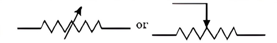
    A resistor whose resistance can be adjusted.
    Ammeter
    An instrument used to measure the current in a circuit, measured in amperes (A).
    Voltmeter
    An instrument used to measure the potential difference (voltage) between two points in a circuit, measured in volts (V).

    Note: 
    The symbols in the table above can be replaced with actual symbols based on standard circuit diagram conventions if needed.

    Ohm's Law

    1. Introduction to Ohm's Law:

    • Question: Is there a relationship between the potential difference (V) across a conductor and the current (I) through it?
    • Activity Objective: To explore the relationship between voltage and current.


    Activity 11.1: Exploring Ohm's Law

    Setup Instructions:

    • Components Needed:
      • Nichrome wire (length: 0.5 m)
      • Ammeter
      • Voltmeter
      • Four cells (1.5 V each)
    • Nichrome Definition: An alloy of nickel, chromium, manganese, and iron metals.

    Procedure:
    1. Single Cell Connection:
      • Connect only one cell as the source in the circuit.
      • Record the readings:
        • Ammeter (I): Current through the nichrome wire.
        • Voltmeter (V): Potential difference across the nichrome wire.
      • Tabulate Results: Record values in the table.
    2. Two Cells Connection:
      • Connect two cells in the circuit.
      • Record the respective readings of the ammeter and voltmeter.
    3. Three Cells Connection:
      • Repeat the process with three cells.
      • Record readings.
    4. Four Cells Connection:
      • Repeat the process with four cells.
      • Record readings.
    5. Calculate Ratio:
      • For each pair of voltage (V) and current (I), calculate the ratio V I \frac{V}{I} IV​.
    6. Graph Plotting:
      • Plot a graph of V against I.
      • Observe the nature of the graph.

    Observations
    • Graph Nature: The graph will be a straight line passing through the origin, indicating a linear relationship between V and I.
    • Constant Ratio: The value of V I \frac{V}{I} ​ is approximately the same in each case.


    Conclusion

    • Ohm’s Law Statement: The potential difference (V) across a conductor is directly proportional to the current (I) flowing through it, expressed mathematically as: V = I × R V = I \times R where R R  is the resistance of the conductor.


    Ohm’s Law and Resistance

    Introduction to Ohm's Law:

    • Discovered by: German physicist Georg Simon Ohm (1787–1854) in 1827.
    • Relationship Found: The potential difference V V  across the ends of a metallic wire is directly proportional to the current I I  flowing through it, given that the temperature remains constant.

    Ohm's Law Statement

    • Expression: V I V \propto I
    • Rearranged Form: V I = constant = R \frac{V}{I} = \text{constant} = R or, equivalently, V = I × R V = I \times R where:
    • V: Potential difference across the conductor.
    • I: Current flowing through the conductor.
    • R: Resistance of the conductor.

    Definition of Resistance (R)

    • Symbol: R R
    • Definition: Resistance is a property of a conductor that opposes the flow of electric charges.
    • SI Unit: Ohm (Ω), represented by the Greek letter omega.
    • Equation for Resistance: R = V I
    • Condition for 1 Ohm: If the potential difference across a conductor is 1 V and the current flowing through it is 1 A, then the resistance R R  of the conductor is 1 Ω.
      • Therefore, 1 Ω = 1 V / 1 A 1 \, \Omega = 1 \, \text{V} / 1 \, \text{A}

    Key Formulae
    1. Ohm’s Law: V = I × R
    2. Current in terms of Resistance and Potential Difference: I = V R

    Relationship Between Current and Resistance
    • Inverse Relationship: According to Ohm’s Law, current I I  is inversely proportional to resistance R R  if the potential difference V V  is constant.
    • Effect of Resistance on Current: If the resistance is doubled, the current is halved, assuming the potential difference remains the same.

    Variable Resistance and Rheostat
    • Purpose of Variable Resistance: Used to increase or decrease the current in an electric circuit without altering the voltage source.
    • Device Used: A rheostat is a device commonly used to change the resistance in an electric circuit, thereby controlling the current.

    Questions
    1. Q: What is Ohm’s Law?
      A: Ohm’s Law states that the potential difference across a conductor is directly proportional to the current flowing through it, provided the temperature remains constant.
    2. Q: Define resistance and state its SI unit.
      A: Resistance is the property of a conductor to resist the flow of charges through it. Its SI unit is the ohm (Ω).
    3. Q: What happens to the current if the resistance in a circuit is doubled, assuming voltage remains constant?
      A: If the resistance is doubled, the current is halved.
    4. Q: What is the role of a rheostat in an electric circuit?
      A: A rheostat is used to adjust the resistance in a circuit, which in turn regulates the current flow without changing the voltage source.


    Activity 11.2: Exploring Current through Different Components

    Objective: To investigate how the current varies when different components are used in a circuit and to understand the concept of resistance in conductors.


    Materials Needed

    • Nichrome wire, Torch bulb, 10 W bulb, Ammeter (0 – 5 A range), Plug key, Connecting wires, Four dry cells (1.5 V each)

    Activity Procedure
    1. Circuit Setup:
      • Connect four dry cells in series (total voltage = 6 V) with the ammeter.
      • Leave a gap X Y XY  in the circuit as shown in Fig. 11.4.
      • Complete the circuit by connecting the nichrome wire in the gap X Y XY .
    2. Measuring Current with Nichrome Wire:
      • Plug in the key and note the ammeter reading.
      • Important Note: Always remove the key from the plug after measuring the current to prevent damage.
    3. Replace with Torch Bulb:
      • Disconnect the nichrome wire and replace it with the torch bulb.
      • Measure the current through the torch bulb using the ammeter.
    4. Replace with 10 W Bulb:
      • Again, remove the previous component and replace it with the 10 W bulb.
      • Measure the current using the ammeter.
    5. Analysis of Results:
      • Question: Are the ammeter readings different for different components connected in the gap X Y XY ?
      • Observation: The readings will vary for different components.
      • Discussion: This indicates that different components offer different levels of resistance to the flow of electric current.

    Observations and Analysis
    • Variation in Current: The current differs for different components because some components provide an easier path for the flow of electric current while others resist it.
    • Electron Movement: In an electric circuit, the flow of electrons constitutes electric current. However, electrons are not entirely free to move due to:
      • Attraction of Atoms: Electrons are attracted to the atoms within the conductor, causing resistance to their flow.

    Understanding Resistance
    • Definition of Resistance: Resistance is the property of a material that opposes the flow of electric current.
    • Classification of Conductors:
      • Good Conductor: A component of a given size that offers low resistance (e.g., copper wire).
      • Resistor: A conductor with appreciable resistance used to control current flow.
      • Poor Conductor: A component of identical size that offers higher resistance.
      • Insulator: A material with very high resistance that does not conduct electricity well (e.g., rubber).

    Conclusion
    • The activity demonstrates that different materials exhibit varying levels of resistance, influencing the amount of current that can flow through them. Components like nichrome wire, bulbs, and resistors affect the flow of electrons differently based on their inherent resistive properties.


    Activity 11.3: Investigating Factors Affecting Resistance

    Objective: To study how resistance varies with length, cross-sectional area, and material type, and its effect on electric current.


    Materials

    • Cell, Ammeter, Nichrome wire (length l, marked (1))
    • Nichrome wire (length 2 l 2l , marked (2))
    • Thicker nichrome wire (length l l , marked (3))
    • Copper wire (length l l , marked (4)), Plug key

    Procedure and Readings
    1. With Nichrome Wire l l  (1):
      • Current: I 1 I_1
    2. With Nichrome Wire 2 l 2l  (2):
      • Current: I 2 I_2
    3. With Thicker Nichrome Wire l l  (3):
      • Current: I 3 I_3
    4. With Copper Wire l l  (4):
      • Current: I 4 I_4

    Observations
    • I 2 < I 1 I_2 < I_1 : Current decreases with increased length.
    • I 3 > I 1 I_3 > I_1 : Current increases with increased cross-sectional area.
    • I 4 > I 1 I_4 > I_1 : Current increases with a better conducting material (copper).

    Conclusion
    • Resistance increases with length and decreases with cross-sectional area. Different materials affect resistance, influencing the current flow.


    Resistance of Conductors

    Observation Summary:

    • The ammeter reading decreases to half when the length of the wire is doubled.
    • The ammeter reading increases with a thicker wire of the same material and length.
    • A change in ammeter reading occurs when a wire of different material (same length and cross-section) is used.

    Key Points
    1. Ohm’s Law Relation:
      • Resistance ( R R ) depends on:
        • Length ( l l ): Directly proportional to length.
                                              R l ( 11.8 ) R \propto l \quad (11.8)
        • Area of Cross-Section ( A A A): Inversely proportional to the area.
                                              R 1 A ( 11.9 ) R \propto \frac{1}{A} \quad (11.9)
    2. Combined Relationship:
      • Combining both relationships gives:
                                               R l A ( 11.10 ) R \propto \frac{l}{A} \quad (11.10)
      • Thus,
                                               R = ρ l A R = \rho \cdot \frac{l}{A}  
        where ρ (rho) is the resistivity of the material.

    Resistivity ( ρ )
    • Definition: A constant that represents how strongly a material opposes the flow of electric current.
    • SI Unit: Ohm meter ( Ω m \Omega \cdot m Ω⋅m).
    • Characteristics:
      • Metals and alloys have low resistivity: 1 0 8 Ω m 10^{-8} \, \Omega \cdot m  to 1 0 6 Ω m 10^{-6} \, \Omega \cdot m  (good conductors).
      • Insulators (e.g., rubber, glass) have high resistivity: 1 0 12 Ω m 10^{12} \, \Omega \cdot m  to 1 0 17 Ω m 10^{17} \, \Omega \cdot m

    Temperature Dependence
    • Both resistance and resistivity vary with temperature.
    • Alloys generally have higher resistivity than their constituent metals.
    • Alloys are preferred for heating devices due to their higher stability at high temperatures.

    Applications
    • Tungsten: Used for filaments in electric bulbs.
    • Copper and Aluminum: Commonly used for electrical transmission lines.

    Type

    Material

    Resistivity (Ω m)

    Conductors Silver 1.60 × 10⁻⁸
    Copper 1.62 × 10⁻⁸
    Aluminium 2.63 × 10⁻⁸
    Tungsten 5.20 × 10⁻⁸
    Nickel 6.84 × 10⁻⁸
    Iron 10.0 × 10⁻⁸
    Chromium 12.9 × 10⁻⁸
    Mercury 94.0 × 10⁻⁸
    Manganese 1.84 × 10⁻⁶
    Alloys Constantan 49 × 10⁻⁶
    (Cu and Ni)
    Manganin 44 × 10⁻⁶
    (Cu, Mn, Ni)
    Nichrome 100 × 10⁻⁶
    (Ni, Cr, Mn, Fe)
    Insulators Glass 10¹⁰ – 10¹⁴
    Hard rubber 10¹³ – 10¹⁶
    Ebonite 10¹⁵ – 10¹⁷
    Diamond 10¹² – 10¹³
    Paper (dry) 10¹²

    Examples

    Example 11.3

    Problem: (a) How much current will an electric bulb draw from a 220 V source if the resistance of the bulb filament is 1200 Ω?
    (b) How much current will an electric heater coil draw from a 220 V source if the resistance of the heater coil is 100 Ω?

    Solution: (a)

    • Given:
      • V = 220 V V = 220 \, \text{V}
      • R = 1200 Ω R = 1200 \, \Omega
    • Calculation: I = V R = 220 V 1200 Ω = 0.18 A
    (b)
    • Given:
      • V = 220 V V = 220 \, \text{V}
      • R = 100 Ω R = 100 \, \Omega
    • Calculation: I = V R = 220 V 100 Ω = 2.2 A I = \frac{V}{R} = \frac{220 \, \text{V}}{100 \, \Omega} = 2.2 \, \text{A}
    Example 11.4

    Problem:
    The potential difference between the terminals of an electric heater is 60 V when it draws a current of 4 A from the source. What current will the heater draw if the potential difference is increased to 120 V?

    Solution:

    • Given:
      • V = 60 V V = 60 \, \text{V}
      • I = 4 A
    • Calculate resistance using Ohm's law: R = V I = 60 V 4 A = 15 Ω
    • For V = 120 V V = 120 \, \text{V} V=120V: I = V R = 120 V 15 Ω = 8 A


    Example 11.5

    Problem:
    Resistance of a metal wire of length 1 m is 26 Ω at 20°C. If the diameter of the wire is 0.3 mm, what will be the resistivity of the metal at that temperature? Using Table 11.2, predict the material of the wire.

    Solution:

    • Given:
      • R = 26 Ω R = 26 \, \Omega
      • Diameter d = 0.3 mm = 0.3 × 1 0 3 m d = 0.3 \, \text{mm} = 0.3 \times 10^{-3} \, \text{m}
      • Length l = 1 m
    • Area of cross-section A A : A = π d 2 4 = π ( 0.3 × 1 0 3 ) 2 4 7.07 × 1 0 8 m 2 A = \frac{\pi d^2}{4} = \frac{\pi (0.3 \times 10^{-3})^2}{4} \approx 7.07 \times 10^{-8} \, \text{m}^2
    • Calculate resistivity: ρ = R A l = 26 Ω 7.07 × 1 0 8 m 2 1 m 1.84 × 1 0 6 Ω m \rho = \frac{RA}{l} = \frac{26 \, \Omega \cdot 7.07 \times 10^{-8} \, \text{m}^2}{1 \, \text{m}} \approx 1.84 \times 10^{-6} \, \Omega \cdot \text{m}
    • Material prediction: From Table 11.2, this resistivity corresponds to manganese.


    Example 11.6

    Problem:
    A wire of given material having length l l l and area of cross-section A A  has a resistance of 4 Ω. What would be the resistance of another wire of the same material having length l 2 \frac{l}{2} ​ and area of cross-section 2 A 2A ?Solution:

    • Given:
      • Resistance of first wire R 1 = 4 Ω R_1 = 4 \, \Omega
      • New wire has:
        • Length l 2 = l 2 l_2 = \frac{l}{2}
        • Area of cross-section A 2 = 2 A A_2 = 2A
    • Calculate resistance of the new wire R 2 R_2 ​:
    • Using R = ρ l A R = \rho \cdot \frac{l}{A} : R 2 = ρ l / 2 2 A = ρ l 4 A = R 1 4 = 4 Ω 4 = 1 Ω

    Activity 11.5: Measuring Potential Difference Across Resistors in Series

    Objective: To understand how potential difference distributes across resistors connected in series.


    Materials Needed
    :

    • Three resistors in series
    • Voltmeter
    • Battery
    • Plug key

    Procedure
    :
    1. Connect a voltmeter across points X and Y in the series combination of resistors (see Fig. 11.6).
    2. Plug the key and record the voltmeter reading as V V V (potential difference across the series combination).
    3. Compare V V V with the potential difference across the battery.
    4. Disconnect the voltmeter, then reconnect it across the first resistor only, measuring the potential difference V 1 V_1 V1​.
    5. Similarly, measure potential differences V 2 V_2 V2​ and V 3 V_3 V3​ across the other two resistors.

    Observation
    :
    The total potential difference V V  across the series combination is equal to the sum of the individual potential differences: V = V 1 + V 2 + V 3 V = V_1 + V_2 + V_3
    Conclusion: 
    In a series circuit, the total resistance R s R_s ​is the sum of individual resistances:
    R s = R 1 + R 2 + R 3

    R_s = R_1 + R_2 + R_3
    This total resistance is greater than any of the individual resistances.

    Example 11.7: Calculation with Resistors in Series

    Problem:
    An electric lamp with resistance R 1 = 20 Ω R_1 = 20 \, \Omega  and a conductor with resistance R 2 = 4 Ω R_2 = 4 \, \Omega  are connected in series to a 6 V battery (see Fig. 11.9). Calculate:
    (a) The total resistance of the circuit,
    (b) The current through the circuit,
    (c) The potential difference across the electric lamp and conductor.

    Solution:(a) Total Resistance
    In a series circuit, total resistance R s R_s Rs​ is the sum of individual resistances: R s = R 1 + R 2 = 20 Ω + 4 Ω = 24 Ω


    (b) Current Through the Circuit

    Using Ohm’s law ( I = V R I = \frac{V}{R} ​), the current I I  is:

    I = V R s = 6 V 24 Ω = 0.25 A I = \frac{V}{R_s} = \frac{6 \, \text{V}}{24 \, \Omega} = 0.25 \, \text{A}

    (c) Potential Difference Across Each Component

    1. Electric Lamp: V 1 = I × R 1 = 0.25 A × 20 Ω = 5 V V_1 = I \times R_1 = 0.25 \, \text{A} \times 20 \, \Omega = 5 \, \text{V}
    2. Conductor: V 2 = I × R 2 = 0.25 A × 4 Ω = 1 V V_2 = I \times R_2 = 0.25 \, \text{A} \times 4 \, \Omega = 1 \, \text{V}
    Equivalent Resistor:
    If we replace the lamp and conductor with a single resistor R R R that maintains the same 6 V and 0.25 A:

    R = V I = 6 V 0.25 A = 24 Ω R = \frac{V}{I} = \frac{6 \, \text{V}}{0.25 \, \text{A}} = 24 \, \Omega

    11.6.2 - Resistors in Parallel

    When resistors are connected in parallel, each resistor is connected across the same potential difference, as shown in Fig. 11.7.

    Activity 11.6

    1. Setup:
      • Create a parallel connection, labeled X Y XY , using three resistors with resistances R 1 R_1 ​, R 2 R_2 ​, and R 3 R_3 ​.
      • Connect this combination with a battery, a plug key, and an ammeter (see Fig. 11.10).
      • Attach a voltmeter across the combination to measure the potential difference.
    2. Procedure:
      • Plug the key into the circuit and record the ammeter reading, representing the total current I I .
      • Take the voltmeter reading to find the potential difference V V  across the combination. Note that the potential difference V V  across each resistor in parallel is the same and can be checked by connecting the voltmeter across each individual resistor (see Fig. 11.11).
      • Remove the plug key, ammeter, and voltmeter from the circuit. Then, place the ammeter in series with R 1 R_1 ​ to measure the current through it, noted as I 1 I_1 ​.
      • Similarly, measure the currents through R 2 R_2 ​ and R 3 R_3 ​ as I 2 I_2 ​ and I 3 I_3 ​, respectively.
    3. Observation:
      • The total current I I I in the circuit equals the sum of the individual branch currents: I = I 1 + I 2 + I 3

    Equivalent Resistance in Parallel

    Let Rp​ be the equivalent resistance of the parallel combination. By applying Ohm's law to the entire combination:

    I = V R p I = \frac{V}{R_p} For each resistor: I 1 = V R 1 , I 2 = V R 2 , I 3 = V R 3 I_1 = \frac{V}{R_1}, \quad I_2 = \frac{V}{R_2}, \quad I_3 = \frac{V}{R_3}

    ​Substituting these values into the total current equation:

    V R p = V R 1 + V R 2 + V R 3 \frac{V}{R_p} = \frac{V}{R_1} + \frac{V}{R_2} + \frac{V}{R_3}
    Dividing by V V  throughout, we get: 1 R p = 1 R 1 + 1 R 2 + 1 R 3 \frac{1}{R_p} = \frac{1}{R_1} + \frac{1}{R_2} + \frac{1}{R_3}
    ​Conclusion: The reciprocal of the equivalent resistance R p R_p in a parallel combination is equal to the sum of the reciprocals of the individual resistances.

    Example 11.8: In the circuit diagram shown in Fig. 11.10, resistors R 1 R_1 ​, R 2 R_2 ​, and R 3 R_3 ​ have values of 5 Ω, 10 Ω, and 30 Ω, respectively, and they are connected in parallel to a 12 V battery.

    Solution:

    1. Given Data:
      • R 1 = 5 Ω R_1 = 5 \, \Omega
      • R 2 = 10 Ω R_2 = 10 \, \Omega
      • R 3 = 30 Ω R_3 = 30 \, \Omega
      • V = 12 V V = 12 \, \text{V}  (battery voltage)
    2. Current through Each Resistor: Since the resistors are in parallel, the potential difference V V  across each resistor is the same and equal to the battery voltage (12 V). Using Ohm's law I = V R I = \frac{V}{R} ​ for each resistor:
      • Current through R 1 R_1 : I 1 = V R 1 = 12 V 5 Ω = 2.4 A
      • Current through R 2 R_2 : I 2 = V R 2 = 12 V 10 Ω = 1.2 A
      • Current through R 3 R_3 ​: I 3 = V R 3 = 12 V 30 Ω = 0.4 A
    3. Total Current in the Circuit: The total current I I  in the circuit is the sum of the currents through each resistor:

      I = I 1 + I 2 + I 3 = 2.4 A + 1.2 A + 0.4 A = 4 A I = I_1 + I_2 + I_3 = 2.4 \, \text{A} + 1.2 \, \text{A} + 0.4 \, \text{A} = 4 \, \text{A}
    4. Total Circuit Resistance: For resistors in parallel, the equivalent resistance R p R_p ​ is given by: 1 R p = 1 R 1 + 1 R 2 + 1 R 3 \frac{1}{R_p} = \frac{1}{R_1} + \frac{1}{R_2} + \frac{1}{R_3} Substituting the values: 1 R p = 1 5 + 1 10 + 1 30 \frac{1}{R_p} = \frac{1}{5} + \frac{1}{10} + \frac{1}{30} ​Calculating each term individually: 1 5 = 0.2 , 1 10 = 0.1 , 1 30 = 0.0333 \frac{1}{5} = 0.2, \quad \frac{1}{10} = 0.1, \quad \frac{1}{30} = 0.0333 Adding them together: 1 R p = 0.2 + 0.1 + 0.0333 = 0.3333 \frac{1}{R_p} = 0.2 + 0.1 + 0.0333 = 0.3333 Thus: R p = 1 0.3333 3 Ω R_p = \frac{1}{0.3333} \approx 3 \, \Omega
    Final Answers:
    • (a) Current through R 1 R_1 : 2.4 A, R 2 R_2 ​: 1.2 A, R 3 R_3 ​: 0.4 A
    • (b) Total current in the circuit: 4 A
    • (c) Total circuit resistance: 3 Ω


    Example 11.9

    In Fig. 11.12, resistors R1​=10Ω, R2​=40Ω, R3​=30Ω, R4​=20Ω, and R5​=60Ω are connected to a 12 V battery.

    Solution

    1. Equivalent Resistance of R 1 R_1 ​ and R 2 R_2 : Since R 1 R_1 ​ and R 2 R_2 ​ are in parallel, we can replace them with an equivalent resistance R R' . 1 R = 1 R 1 + 1 R 2 = 1 10 + 1 40 = 5 40 \frac{1}{R'} = \frac{1}{R_1} + \frac{1}{R_2} = \frac{1}{10} + \frac{1}{40} = \frac{5}{40}
      R = 40 5 = 8 Ω R' = \frac{40}{5} = 8 \, \Omega
    2. Equivalent Resistance of R 3 R_3 ​, R 4 R_4 ​, and R 5 R_5 : Since R 3 R_3 ​, R 4 R_4 ​, and R 5 R_5 ​ are also in parallel, we can replace them with an equivalent resistance R R'' . 1 R = 1 R 3 + 1 R 4 + 1 R 5 = 1 30 + 1 20 + 1 60 = 6 60 \frac{1}{R''} = \frac{1}{R_3} + \frac{1}{R_4} + \frac{1}{R_5} = \frac{1}{30} + \frac{1}{20} + \frac{1}{60} = \frac{6}{60}
      R = 60 6 = 10 Ω R'' = \frac{60}{6} = 10 \, \Omega
    3. Total Resistance in the Circuit: Since R R'  and R R'' are in series, the total resistance R R R of the circuit is the sum of R R'  and R R'' : R = R + R = 8 Ω + 10 Ω = 18 Ω

    4. Total Current in the Circuit: Using Ohm’s law to calculate the total current I I : I = V R = 12 V 18 Ω = 0.67 A
    Final Answers:
    • (a) The total resistance in the circuit is 18 Ω \Omega .
    • (b) The total current flowing in the circuit is 0.67 A.
    Additional Explanation:
    • Series Circuit Limitation: In a series circuit, the current is the same throughout, which is impractical for devices needing different currents, like a bulb and heater. If one component fails, the entire circuit breaks, as often seen in decorative "fairy lights."
    • Parallel Circuit Advantage: A parallel circuit divides the current among devices, reducing total resistance and allowing each device to receive the required current independently.

    11.7 - Heating Effect of Electric Current

    A battery or cell acts as a source of electrical energy, generating a potential difference that sets electrons in motion, causing current to flow through a resistor or a combination of resistors. In maintaining this current, the battery expends energy, part of which is used for useful work (e.g., rotating a fan), while the rest is often converted into heat, raising the temperature of the device.

    In cases where the circuit is purely resistive (only resistors connected to a battery), the entire energy from the battery is dissipated as heat. This phenomenon is known as the heating effect of electric current and is applied in devices such as electric heaters and irons.

    Derivation of Heat Produced in a Resistor

    Consider a current I flowing through a resistor of resistance R, with a potential difference V across it over time t. If Q is the charge passing through the resistor, the work done to move Q through V is:

    Work done = V Q \text{Work done} = VQ
    Since power P P  is the energy per unit time, the power supplied to the circuit is: P = V Q t = V I

    P = \frac{VQ}{t} = VI
    The energy supplied over time t t , therefore, is:

    Energy supplied = V I t

    \text{Energy supplied} = VIt
    This energy is dissipated as heat in the resistor. So, the heat H H  produced over time t t  is: H = V I t

    H = VIt
    By substituting Ohm's law ( V = I R V = IR ) into this equation, we get:

    H = I 2 R t

    H = I^2 Rt
    This is known as Joule’s Law of Heating, which states that the heat
    H
    H produced in a resistor is:
    1. Directly proportional to the square of the current ( I 2 I^2 ) for a given resistance.
    2. Directly proportional to the resistance R R  for a given current.
    3. Directly proportional to the time t t  for which the current flows through the resistor.
    In practical applications, when an appliance is connected to a known voltage source, the heating effect can be calculated by first determining the current using I = V R I = \frac{V}{R} ​.


    Example 11.10: An electric iron consumes power at different rates when its heating is adjusted. The power consumption is 840 W at maximum heating and 360 W at minimum heating, with a voltage supply of 220 V. We need to find the current and resistance in each case.

    Solution: Using the formula for power:

    P = V I P = V \cdot I Thus, the current I = P V I = \frac{P}{V}


    (a) When heating is at the maximum rate (840 W):
    I = 840 W 220 V = 3.82 A I = \frac{840 \, \text{W}}{220 \, \text{V}} = 3.82 \, \text{A} The resistance R R  of the electric iron is: R = V I = 220 V 3.82 A = 57.60 Ω R = \frac{V}{I} = \frac{220 \, \text{V}}{3.82 \, \text{A}} = 57.60 \, \Omega
    (b) When heating is at the minimum rate (360 W):
    I = 360 W 220 V = 1.64 A I = \frac{360 \, \text{W}}{220 \, \text{V}} = 1.64 \, \text{A} The resistance R R  is: R = V I = 220 V 1.64 A = 134.15 Ω R = \frac{V}{I} = \frac{220 \, \text{V}}{1.64 \, \text{A}} = 134.15 \, \Omega

    Example 11.11: Given: A 4 Ω resistor produces 100 J of heat each second. We need to find the potential difference across this resistor.

    Solution: Heat H=100J, Resistance R=4Ω, Time t=1s, and V=?. Using the formula from Joule’s Law of Heating:

    H = I 2 R t H = I^2 R t Rearrange to find I I I: I = H R t = 100 J 4 Ω × 1 s = 5 A I = \sqrt{\frac{H}{R t}} = \sqrt{\frac{100 \, \text{J}}{4 \, \Omega \times 1 \, \text{s}}} = 5 \, \text{A}
    Now, using Ohm's law to find the potential difference:
    V =  I 5 ×  4 Ω  20 V

    So, the potential difference across the resistor is

    V = 20 V V = 20 \, \text{V} .

    11.7.1 - Practical Applications of Heating Effect of Electric Current

    The heating effect of electric current, a phenomenon resulting from the flow of electric current through a conductor, has both undesirable and beneficial implications. While unwanted heating can alter the properties of circuit components and convert useful electrical energy into heat, it also finds numerous practical applications:

    1. Electric Heating Appliances: Devices like electric irons, toasters, ovens, kettles, and heaters utilize Joule’s heating to convert electrical energy into thermal energy for cooking, heating, and ironing.
    2. Electric Bulbs: In electric bulbs, the filament generates heat due to current flow. To produce light, the filament must reach a high temperature without melting, which is why materials like tungsten (with a melting point of 3380°C) are used. The bulb's filament is thermally insulated, and gases like nitrogen and argon are used to fill the bulb, prolonging the filament's life by preventing oxidation.
    3. Fuses: A critical safety device in electrical circuits, fuses prevent damage from excessive current flow. A fuse contains a wire made from a metal or alloy with a specific melting point (such as aluminum, copper, iron, or lead). When current exceeds a predetermined level, the fuse wire heats up and melts, breaking the circuit and stopping the current flow. Fuses are encased in materials like porcelain and come in various ratings, such as 1 A, 2 A, 3 A, 5 A, and 10 A.
      • Example: For an electric iron that consumes 1 kW of power at 220 V, the current can be calculated as:
      I = P V = 1000 W 220 V 4.54 A I = \frac{P}{V} = \frac{1000 \, \text{W}}{220 \, \text{V}} \approx 4.54 \, \text{A} In this case, a fuse rated at 5 A would be appropriate to protect the circuit.
    Overall, while the heating effect can be a nuisance in some electrical devices, it is harnessed effectively for various applications that enhance our daily lives.

    11.8 - Electric Power

    Electric power is defined as the rate at which electrical energy is consumed or dissipated in an electric circuit. It is a measure of how quickly work is done or energy is consumed in an electrical system. The power P P  can be expressed in several forms:

    1. Basic Power Equation: P = V I P = VI Where:
      • P P  = Power (in watts)
      • V V  = Voltage (in volts)
      • I I  = Current (in amperes)
    2. Alternate Forms:
      • Using Ohm's law ( V = I R V = IR ): P = I 2 R P = I^2R
      • Rearranging Ohm's law gives: P = V 2 R P = \frac{V^2}{R}
    Units of Electric Power
    • The SI unit of electric power is the watt (W), defined as the power consumed by a device carrying a current of 1 A at a potential difference of 1 V: 1 W = 1 V × 1 A 1 \, \text{W} = 1 \, \text{V} \times 1 \, \text{A}
    • Since the watt is a relatively small unit, kilowatt (kW), which equals 1000 watts, is commonly used in practice.


    Electrical Energy

    Electrical energy is the product of power and time, leading to the unit of electric energy being measured in watt-hours (Wh). One watt-hour is the energy consumed when 1 watt of power is used for 1 hour. The commercial unit of electric energy is the kilowatt-hour (kWh), often referred to as a "unit."

    • Conversion from watts to kilowatt-hours: 1 kWh = 1000 W × 3600 s = 3.6 × 1 0 6 W s = 3.6 × 1 0 6 J 1 \, \text{kWh} = 1000 \, \text{W} \times 3600 \, \text{s} = 3.6 \times 10^6 \, \text{W s} = 3.6 \times 10^6 \, \text{J}
    This understanding of electric power is essential for calculating energy consumption in various electrical devices and for managing energy efficiency in households and industries.


    More to Know!

    It is a common misconception that electrons are consumed in an electric circuit. In reality, we pay for the energy supplied by electricity providers to move electrons through electrical devices like bulbs, fans, and engines. The energy we are charged for reflects the power consumed by these devices over time, not the electrons themselves.

    Example 11.12 Power of an Electric Bulb

    An electric bulb is connected to a 220 V generator, and the current flowing through it is 0.50 A. To find the power of the bulb, we can use the formula for electric power:

    P = V I P = VI Substituting the values: P = 220 V × 0.50 A = 110 J/s = 110 W P = 220 \, \text{V} \times 0.50 \, \text{A} = 110 \, \text{J/s} = 110 \, \text{W}


    Example 11.13 Cost of Operating an Electric Refrigerator

    Given:

    • Power rating of the refrigerator: 400 W
    • Operating time: 8 hours/day
    • Duration: 30 days
    • Cost of electricity: Rs 3.00 per kWh
    Step 1: Calculate Total Energy Consumption

    First, calculate the total energy consumed by the refrigerator over 30 days:

    Total Energy = Power × Time × Days

    Total Energy = 400 W × 8 hours/day × 30 days = 96000 W h = 96 kW h \text{Total Energy} = 400 \, \text{W} \times 8 \, \text{hours/day} \times 30 \, \text{days} = 96000 \, \text{W h} = 96 \, \text{kW h}
    Step 2: Calculate the Cost of Energy

    Now, we can find the cost to operate the refrigerator for 30 days:

    Cost = Total Energy × Cost per kWh \text{Cost} = \text{Total Energy} \times \text{Cost per kWh}
    Cost = 96 kW h × Rs 3.00/kW h = Rs 288.00 \text{Cost} = 96 \, \text{kW h} \times \text{Rs 3.00/kW h} = \text{Rs 288.00}
    Summary
    • The electric bulb has a power of 110 W.
    • The cost of operating the refrigerator for 30 days is Rs 288.00.
    Understanding these calculations is important for managing energy consumption and costs effectively in our daily lives.

    NCERT Science Notes - Class 10 | Science | Chapter - 11 | Electricity

    NCERT Science Notes - Class 10 | Science | Chapter - 11 | Electricity

    OUR SERVICES

    Doubt Solving 1-on-1

    Dedicated team provides prompt assistance and individual guidance.

    NCERT Visualized

    Engaging visuals enhance understanding of complex concepts.

    Career Counselling

    Engaging visuals enhance understanding of complex concepts.

    Section-wise Tests

    Assess understanding and track progress through topic-specific tests

    Contact Us

    Course Feedback